|
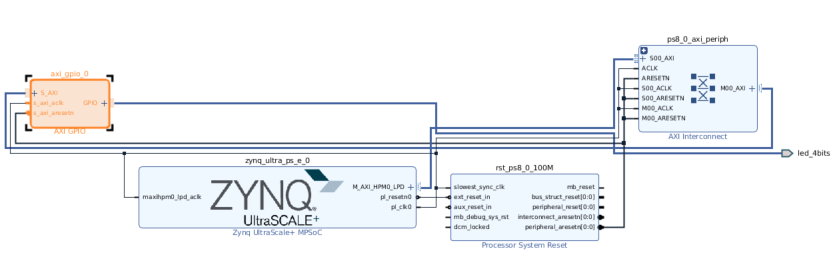
Linux 嵌入式设计中最基本的任务之一是创建用户应用程序。 在本篇博文中,我们将探讨如何在 Vitis 中使用 UIO 驱动框架创建简单的 Linux 用户应用。 1 硬件设计 本次使用的是 Zynq UltraScale+ MPSoC ZCU104 评估板。但是,无论您使用任何器件,下列步骤都应适用。 先使用 Vivado 来创建了块设计。建立了 Zynq UltraScale PS,并把 AXI GPIO 连接到 ZCU104 评估板上的 4 个 LED。
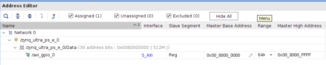
地址映射如下所示:
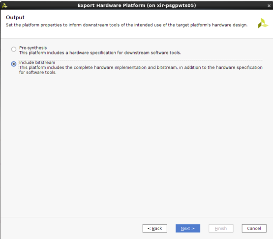
首先 在创建 XSA 时使用了以下选项:
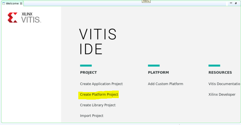
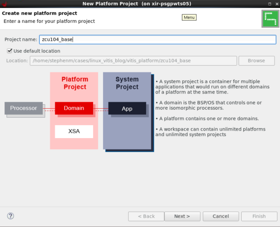
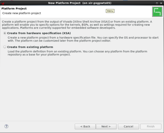
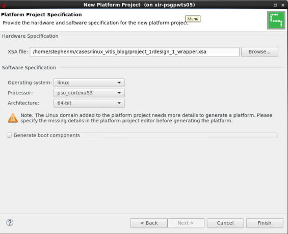
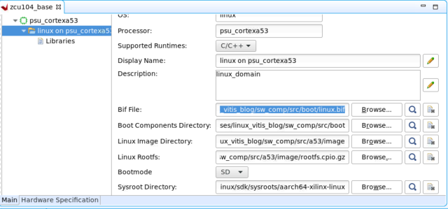
2 Linux 镜像 如果您使用开发板,则建议使用 BSP(如果存在)。 但在本示例中,我们使用模板来创建镜像。已经添加了 UIO 驱动程序,用于 AXI GPIO。 然后创建了 sysroot,在 Vitis 中需要使用它来进行交叉编译。 petalinux-create -t project --template zynqMP -n zcu104_linux cd zcu104_linux petalinux-config --get-hw-description=依次选择“DTG Settings -> (zcu104-revc)MACHINE_NAME” petalinux-config -c kernel 将 system-user.dtsi 替换为: /include/ "system-conf.dtsi" / { chosen { bootargs = "earlycon clk_ignore_unused uio_pdrv_genirq.of_id=generic-uio"; stdout-path = "serial0:115200n8"; }; }; &axi_gpio_0 { compatible = "generic-uio"; }; 然后,运行以下命令: petalinux-build cd images/linux2 V8 f/ h, D) I4 Q3 [1 `6 S 3 创建平台 这并非必要步骤,因为用户只需在 Vitis 中使用 sysroot 即可。 但为了便于使用,我们可以创建一个平台并在 Vitis 中使用此平台来创建 Linux 应用。 首先,设置平台文件。 把平台文件组织为一种文件夹结构。这并非必要步骤,但用户需要注意 BIF 中的文件路径。 在 Bootgen 中使用 BIF 来创建可启动的镜像。此处我们仅使用占位符文件名。 mkdir -p sw_comp/src/a53/xrt/image, A' f" X6 [& ~0 T, v) e 将 image.ub、boot.scr 和 rootfs.cpio.gz 文件从 PetaLinux image/linux 文件夹复制到sw_comp/src/a53/image 将 system.bit、bl31.elf、uboot.elf、zynqmp_fsbl(已重命名为 fsbl.elf)和 pmufw.elf 文件从 PetaLinux image/linux 文件夹复制到sw_comp/src/boot 创建 BIF: the_ROM_image: { [fsbl_config] a53_x64 [bootloader] [pmufw_image] [destination_device=pl] [destination_cpu=a53-0, exception_level=el-3, trustzone] [destination_cpu=a53-0, exception_level=el-2] } 将 linux.bif 复制到sw_comp/src/boot。现在,在 Vitis 中创建一个新平台工程,如下所示:
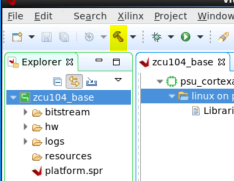
这样就会在zcu104_base/export中创建平台。 4 在 Vitis 中创建 Linux 镜像
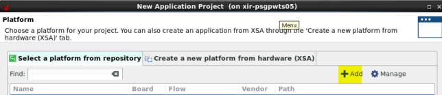
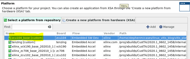
选择“从存储库中选择平台 (Select a platform from therepository)”,单击 + 图标并浏览至您的平台。
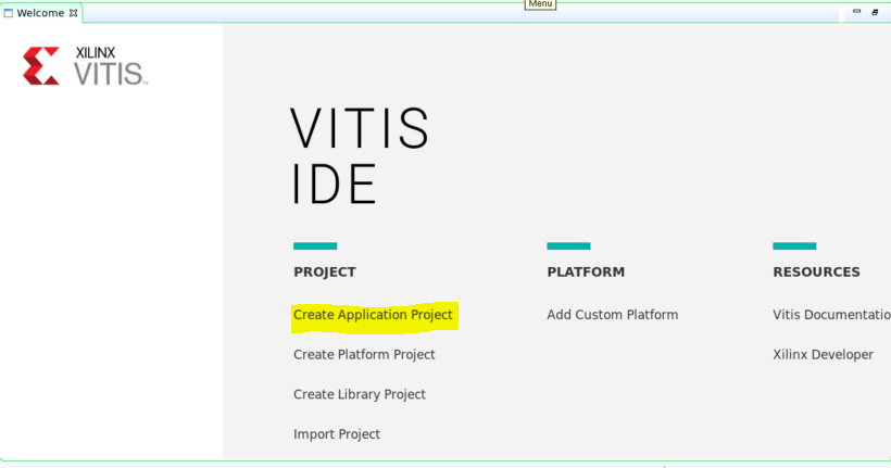
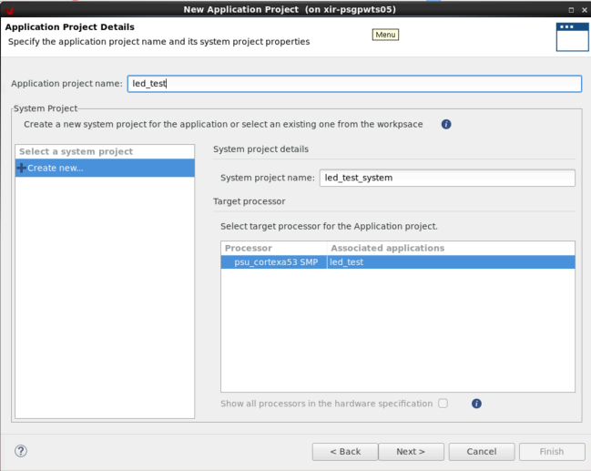
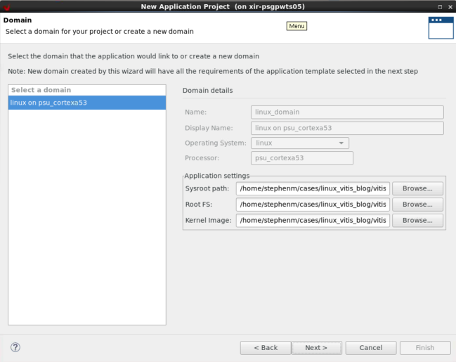
创建新应用:
此处可以看到,“应用设置 (Application settings)”默认使用的是平台中的设置。
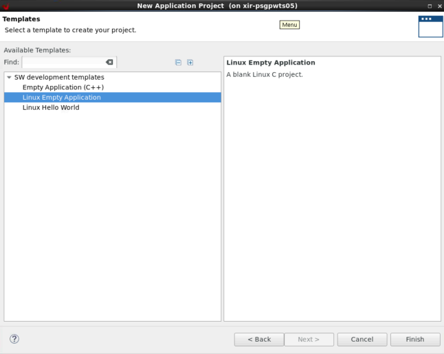
选择“空白应用 (Empty Application)”模板,因为我们将创建自己的自定义应用。
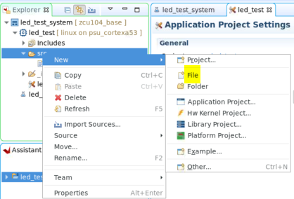
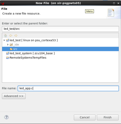
右键单击 led_test 应用下的 src 文件夹,然后选择“新建 (New)”->“文件 (File)”
指定其文件名 (.c),然后单击“完成 (Finish)”。
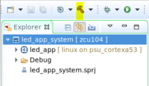
现在,即可将以下代码复制到其中。这是一个简单的 UIO 示例,可用于开关 LED。 #include #include #include #include #include #define GPIO_MAP_SIZE 0x10000 #define GPIO_DATA 0x00 #define GPIO_TRI 0x04 #define LED_NUM 256 #define LED_DELAY 10000000 int main(int argc, char *argv[]) { int fd; char *uiod = "/dev/uio0"; void *gpio_ptr; volatile int Delay; printf("AXI GPIO UIO test. "); // open the UIO device file to allow access to the device in user space fd = open(uiod, O_RDWR); if (fd < 1) { printf("Invalid UIO device file:%s. ", uiod); return -1; } // mmap the GPIO device into user space gpio_ptr = mmap(NULL, 4096, PROT_READ|PROT_WRITE, MAP_SHARED, fd, 0); if (gpio_ptr == MAP_FAILED) { printf("Mmap call failure. "); return -1; } // set bit0 on the GPIO to be output // see pg144 for ref *((volatile unsigned *)(gpio_ptr + GPIO_TRI)) = 0x0; // Toggle the LED while (1) { int i; unsigned char led_pin = 0x0; for (i = 0; i < LED_NUM; i++) { *((volatile unsigned *)(gpio_ptr + GPIO_DATA)) = led_pin; for (Delay = 0; Delay < LED_DELAY; Delay++); *((volatile unsigned *)(gpio_ptr + GPIO_DATA)) = 0x0; led_pin++; } } // unmap the GPIO device from user space munmap(gpio_ptr, 4096); return 0; } 选择系统工程,然后单击锤子图标。这样即可构建可执行文件,并创建启动镜像。
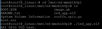
5 在硬件上执行测试 将所有镜像从led_app_systemDebugsd_card复制到 SD 卡上。
启动后,将自动装载 SD 卡。 在此处更改目录,并执行led_app.elf,如下所示:
同时,您在板上应该还可以看到 LED 闪烁。 使用 Ctrl + c 即可取消。 / s% Y, v7 ]4 c8 Q |
【银杏科技ARM+FPGA双核心应用】STM32H7系列10——ADC
【银杏科技ARM+FPGA双核心应用】STM32H7系列57——MDK_FLM
【STM32图书分享之九】—《STM32F 32位ARM微控制器应用设计与实践》
无刷直流电机控制应用+基于STM8S系列单片机---电子书
STM32 USB的程序,包含固件、驱动和测试用的应用程序
工业以太网总线ETHERCAT驱动程序设计及应用(扫描版)
【实战经验】STM32 DFSDM测量温度应用
【实战经验】基于STM32 I2S的音频应用开发介绍
【中文文档】AN4112_使用STM32F05xx模拟比较器的六个应用案例
[连载]STM32F103ZET6 uCGUI3.90a控件应用教程(第五节 复选框和单选按钮)