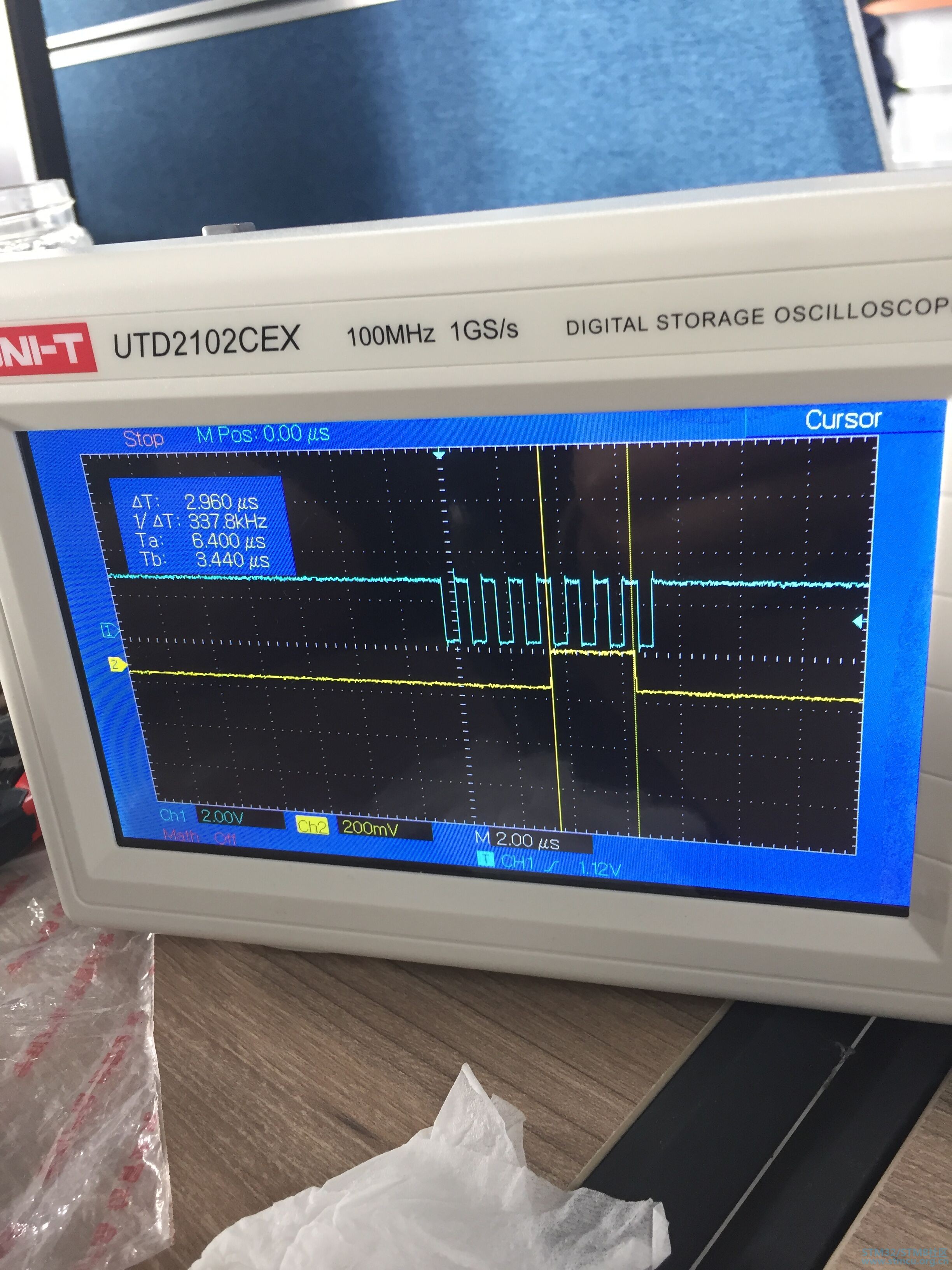
最近在做一个NFC的项目,但是,正在调试CR95HF这款芯片时,卡在了SPI通信这块,CR95HF的原官方库例程使用的CPU芯片是F1和F4系列的,我自己的项目中使用的CPU芯片是F0系列的,现在我的问题是使用CR95HF芯片执行初始化过程时,发送轮询polling命令,接收到的数据始终为0x00,由CR95HF的数据手册可知,发送轮询命令,回复的数据应该是0x08,才是正确数据。使用示波器检测波形,不断发送轮询命令时,MISO引脚(黄色),SCK引脚(白色)的波形图如下。SPI的通信部分代码我也粘贴在下面,求助大家帮我分析一下原因。
SPI通信部分代码: /** * @brief This function initialize the NFC chip * @brief Physical communication with chip enabled, RF communication not enabled * @param None * @retval None */ void ConfigManager_HWInit (void) { /* Initialize HW according to protocol to use */ ConfigManager_Init(); /* initilialize the RF transceiver */ if (ConfigManager_PORsequence( ) != MANAGER_SUCCESSCODE) { /* nothing to do, this is a trap for debug purpose you can use it to detect HW issue */ /* or GPIO config issue */ } /* Retrieve the IC version of the chip */ ConfigManager_IDN(u95HFBuffer); IcVers = (IC_VERSION) (u95HFBuffer[ROM_CODE_REVISION_OFFSET]); } /** * @brief This function initialize the PICC * @param None * @retval None */ static void ConfigManager_Init( void) { /* initialize the structure of the Rf tranceiver */ drv95HF_InitConfigStructure (); #ifdef SPI_INTERRUPT_MODE_ACTIVATED /* inform driver to use interrupt mode */ drv95HF_EnableInterrupt ( ); #endif /* SPI_INTERRUPT_MODE_ACTIVATED */ /* configure the Serial interface to communicate with the RF transceiver */ drv95HF_InitilizeSerialInterface ( ); } /** * @brief Initilize the 95HF device config structure * @param None * @retval None */ void drv95HF_InitConfigStructure (void) { drv95HFConfig.uInterface = RFTRANS_95HF_INTERFACE_SPI; drv95HFConfig.uSpiMode = RFTRANS_95HF_SPI_POLLING; drv95HFConfig.uState = RFTRANS_95HF_STATE_POWERUP; drv95HFConfig.uCurrentProtocol = RFTRANS_95HF_PROTOCOL_UNKNOWN; drv95HFConfig.uMode = RFTRANS_95HF_MODE_UNKNOWN; } /** * @brief This function initialize MCU serial interface peripheral (SPI or UART) * @param None * @retval None */ void drv95HF_InitilizeSerialInterface(void) { /* -- Set communication type -- */ drv95HFConfig.uInterface = RFTRANS_95HF_INTERFACE_SPI; /* -- Initialize SPI Interface -- */ drv95HF_InitializeSPI( ); } /** * @brief this functions initializes the SPI in order to communicate with the 95HF device * @param None * @retval void */ static void drv95HF_InitializeSPI(void) { RFTRANS_SPI_Init(); } /** * @brief Initialise HAL SPI for NFC03A1 * @param None * @retval None */ void RFTRANS_SPI_Init(void) { if(HAL_SPI_GetState(&SpiHandle) == HAL_SPI_STATE_RESET) { /* SPI Config */ SpiHandle.Instance = RFTRANS_95HF_SPI; /* SPI baudrate is set to 12,5 MHz maximum (PCLK2/SPI_BaudRatePrescaler = 100/8 = 12,5 MHz) to verify these constraints: - ST7735 LCD SPI interface max baudrate is 15MHz for write and 6.66MHz for read Since the provided driver doesn't use read capability from LCD, only constraint on write baudrate is considered. - SD card SPI interface max baudrate is 25MHz for write/read - PCLK2 max frequency is 100 MHz */ SpiHandle.Init.Mode = SPI_MODE_MASTER; SpiHandle.Init.BaudRatePrescaler = SPI_BAUDRATEPRESCALER_64; SpiHandle.Init.NSS = SPI_NSS_SOFT; SpiHandle.Init.CLKPolarity = SPI_POLARITY_HIGH; SpiHandle.Init.CLKPhase = SPI_PHASE_2EDGE; SpiHandle.Init.Direction = SPI_DIRECTION_2LINES; SpiHandle.Init.DataSize = SPI_DATASIZE_8BIT; SpiHandle.Init.FirstBit = SPI_FIRSTBIT_MSB; SpiHandle.Init.TIMode = SPI_TIMODE_DISABLE; SpiHandle.Init.CRCCalculation = SPI_CRCCALCULATION_DISABLE; SpiHandle.Init.CRCPolynomial = 7; SpiHandle.Init.CRCLength = SPI_CRC_LENGTH_DATASIZE; SpiHandle.Init.NSSPMode = SPI_NSS_PULSE_ENABLE; /* Initialization SPI*/ if(HAL_SPI_Init(&SpiHandle) != HAL_OK) { /* Initialization Error */ Error_Handler(); } } } /** * @brief SPI MSP Initialization * This function configures the hardware resources used in this example: * - Peripheral's clock enable * - Peripheral's GPIO Configuration * @param hspi: SPI handle pointer * @retval None */ void HAL_SPI_MspInit(SPI_HandleTypeDef *hspi) { GPIO_InitTypeDef GPIO_InitStruct; if(hspi->Instance == RFTRANS_95HF_SPI) { /*##-1- Enable peripherals and GPIO Clocks #################################*/ /* Enable GPIO TX/RX clock */ SPIx_SCK_GPIO_CLK_ENABLE(); SPIx_MISO_GPIO_CLK_ENABLE(); SPIx_MOSI_GPIO_CLK_ENABLE(); SPIx_NSS_GPIO_CLK_ENABLE(); __HAL_RCC_GPIOF_CLK_ENABLE(); /* Enable SPI clock */ SPIx_CLK_ENABLE(); /*##-2- Configure peripheral GPIO ##########################################*/ /* SPI SCK GPIO pin configuration */ GPIO_InitStruct.Pin = RFTRANS_95HF_SPI_SCK_PIN; GPIO_InitStruct.Mode = GPIO_MODE_AF_PP; GPIO_InitStruct.Pull = GPIO_PULLUP; GPIO_InitStruct.Speed = GPIO_SPEED_FREQ_HIGH; GPIO_InitStruct.Alternate = GPIO_AF0_SPI2; HAL_GPIO_Init(RFTRANS_95HF_SPI_SCK_GPIO_PORT, &GPIO_InitStruct); /* SPI MISO GPIO pin configuration */ GPIO_InitStruct.Pin = RFTRANS_95HF_SPI_MISO_PIN; GPIO_InitStruct.Mode = GPIO_MODE_INPUT; GPIO_InitStruct.Pull = GPIO_PULLUP; GPIO_InitStruct.Speed = GPIO_SPEED_FREQ_HIGH; GPIO_InitStruct.Alternate = GPIO_AF0_SPI2;; HAL_GPIO_Init(RFTRANS_95HF_SPI_MISO_GPIO_PORT, &GPIO_InitStruct); /* SPI MOSI GPIO pin configuration */ GPIO_InitStruct.Pin = RFTRANS_95HF_SPI_MOSI_PIN; GPIO_InitStruct.Mode = GPIO_MODE_AF_PP; GPIO_InitStruct.Pull = GPIO_PULLDOWN; GPIO_InitStruct.Speed = GPIO_SPEED_FREQ_HIGH; GPIO_InitStruct.Alternate = GPIO_AF0_SPI2; HAL_GPIO_Init(RFTRANS_95HF_SPI_MOSI_GPIO_PORT, &GPIO_InitStruct); /* SPINSS as output push pull */ GPIO_InitStruct.Pin = RFTRANS_95HF_SPI_NSS_PIN; GPIO_InitStruct.Mode = GPIO_MODE_OUTPUT_PP; GPIO_InitStruct.Pull = GPIO_NOPULL; GPIO_InitStruct.Speed = GPIO_SPEED_FREQ_HIGH; GPIO_InitStruct.Alternate = GPIO_AF0_SPI2; HAL_GPIO_Init(RFTRANS_95HF_SPI_NSS_GPIO_PORT, &GPIO_InitStruct); /* SPI_NSS = High Level */ RFTRANS_95HF_NSS_HIGH(); /* Configure Mcu IRQ_IN GPIO pin GPIO_InitStruct.Pin = IRQOUT_RFTRANS_95HF_PIN; GPIO_InitStruct.Mode = GPIO_MODE_IT_FALLING; GPIO_InitStruct.Pull = GPIO_PULLUP; GPIO_InitStruct.Speed = GPIO_SPEED_FREQ_LOW; HAL_GPIO_Init(IRQOUT_RFTRANS_95HF_PORT, &GPIO_InitStruct); /* Configure Mcu IRQ_OUT pin as open drain output */ GPIO_InitStruct.Pin = IRQIN_RFTRANS_95HF_PIN; GPIO_InitStruct.Mode = GPIO_MODE_OUTPUT_PP; GPIO_InitStruct.Pull = GPIO_NOPULL; GPIO_InitStruct.Speed = GPIO_SPEED_FREQ_HIGH; HAL_GPIO_Init(IRQIN_RFTRANS_GPIO_PORT, &GPIO_InitStruct); /* Set signal to high */ RFTRANS_95HF_IRQIN_HIGH(); } } |

如果示波器波形是MISO(主入从出)的话,数据明显是0x0E,那么这个是什么时候收到的?
你的代码不完整,波形也不完整。如果你的波形是下图最后一个字节的话,那么有什么不对的吗?
评分
查看全部评分
多谢大哥的回复,我找到原因了,是由于自己将MISO配置为了GPIO_MODE_INPUT(浮空输入模式),原来的CR95HF芯片库中是直接设置成上拉模式的,我将它设置成了GPIO_MODE_INPUT模式,就导致我MISO引脚不能正常接收到数据。(最终的原因是什么引起的,还不知道)
评分
查看全部评分
我现在有一个问题,用的ST95HF,返回值全是0x0e,不清楚是怎么回事,根据手册的话,返回值的第一位应该一定是1,我这个结果跟手册完全不同,想请问一下有哪些可能呢
<Result Code> = 0x0e
<Length> = 0x0e
<data> = 0x0e,0x0e,0x0e,0x0e,0x0e,0x0e,0x0e,0x0e,0x0e,0x0e,0x0e,0x0e,0x0e,0x0e